Suspension software, particularly Adams Car, is vital for automotive engineers. This article from CAR-REMOTE-REPAIR.EDU.VN will explore the capabilities of Adams Car in suspension design, its role in vehicle dynamics, and how you can master its use through specialized training, enhancing your skills in remote automotive repair and diagnostics. Learning about kinematic and compliance analysis will set you up for success in automotive technology.
Contents
- 1. What is Suspension Software Adams Car?
- 1.1. Key Capabilities of Adams Car
- 1.2. Benefits of Using Adams Car
- 1.3. How Adams Car Works
- 1.4. Real-World Applications
- 2. How Does Adams Car Suspension Software Enhance Vehicle Dynamics Analysis?
- 2.1. Comprehensive Simulation Capabilities
- 2.2. Predicting Vehicle Behavior
- 2.3. Optimizing Vehicle Performance
- 2.4. Validating Design Decisions
- 2.5. Integration with Testing
- 3. What Are the Benefits of Kinematic and Compliance Analysis in Suspension Design Using Adams Car?
- 3.1. Optimizing Suspension Geometry
- 3.2. Improving Vehicle Handling
- 3.3. Enhancing Ride Comfort
- 3.4. Compliance Effects
- 3.5. Design Validation
- 4. What Are the Key Steps in Setting Up a Suspension Model in Adams Car?
- 4.1. Defining the Scope and Objectives
- 4.2. Gathering Data
- 4.3. Creating the Model
- 4.4. Modeling Components
- 4.5. Applying Loads and Boundary Conditions
- 4.6. Running Simulations
- 4.7. Analyzing Results
- 4.8. Iterating and Optimizing
- 5. How Can You Model Different Suspension Types in Adams Car?
- 5.1. MacPherson Strut Suspension
- 5.2. Double Wishbone Suspension
- 5.3. Multi-Link Suspension
- 5.4. Solid Axle Suspension
- 5.5. Air Suspension
- 5.6. Torsion Bar Suspension
- 6. What Is the Role of Bushings and Joints in Adams Car Suspension Simulations?
- 6.1. Bushings
- 6.2. Joints
- 6.3. Best Practices for Modeling Bushings and Joints
- 6.4. Examples of Bushing and Joint Applications
- 7. What Techniques Can Be Used for Validating Adams Car Suspension Models?
- 7.1. Experimental Testing
- 7.2. Component Testing
- 7.3. Theoretical Analysis
- 7.4. Data Correlation
- 7.5. Sensitivity Analysis
- 8. How Can Adams Car Be Integrated with Other CAE Software?
- 8.1. Finite Element Analysis (FEA) Software
- 8.2. Computational Fluid Dynamics (CFD) Software
- 8.3. Control Systems Software
- 8.4. CAD Software
- 8.5. Multi-Physics Simulation Software
- 9. What Are the Advanced Features of Adams Car for Suspension Analysis?
- 9.1. Flexbody Analysis
- 9.2. Co-Simulation with Control Systems
- 9.3. Design of Experiments (DOE)
- 9.4. Optimization Algorithms
- 9.5. User-Defined Subroutines
- 9.6. Advanced Tire Models
- 10. How Can Training at CAR-REMOTE-REPAIR.EDU.VN Help You Master Suspension Software Adams Car?
- 10.1. Comprehensive Curriculum
- 10.2. Hands-On Experience
- 10.3. Expert Instructors
- 10.4. State-of-the-Art Facilities
- 10.5. Career Advancement
1. What is Suspension Software Adams Car?
Suspension Software Adams Car is a multibody dynamics simulation software widely used in the automotive industry for designing and analyzing vehicle suspension systems. It allows engineers to model and simulate the behavior of vehicle suspensions under various operating conditions, which helps in optimizing performance, ride quality, and handling.
Adams Car, a product of MSC Software (now part of Hexagon), is essentially a specialized version of the Adams (Automatic Dynamic Analysis of Mechanical Systems) software tailored for automotive applications. It provides a virtual proving ground where engineers can test and refine their designs before building physical prototypes.
1.1. Key Capabilities of Adams Car
- Kinematics and Compliance Analysis: Adams Car enables detailed analysis of suspension geometry and its effect on wheel movement, steering, and vehicle stability. According to a study by the University of Michigan Transportation Research Institute in 2024, accurate kinematic analysis is crucial for predicting vehicle handling characteristics.
- Full Vehicle Simulation: Beyond suspension, Adams Car can simulate the entire vehicle, including powertrain, steering, and braking systems. This comprehensive approach allows engineers to understand how different systems interact and affect overall vehicle performance.
- Durability Testing: The software can simulate real-world driving conditions, including rough roads and aggressive maneuvers, to assess the durability of suspension components. This helps in identifying potential failure points and optimizing designs for longevity.
- Integration with CAD Software: Adams Car integrates with popular CAD (Computer-Aided Design) software, such as CATIA and SolidWorks, allowing seamless transfer of design data and efficient collaboration between design and simulation teams.
- Customization: Adams Car is highly customizable, allowing users to define their own parameters, create custom routines, and tailor the software to their specific needs.
1.2. Benefits of Using Adams Car
- Reduced Prototyping Costs: By simulating vehicle behavior in a virtual environment, Adams Car reduces the need for physical prototypes, which can be expensive and time-consuming to build and test.
- Improved Performance: The software allows engineers to optimize suspension designs for specific performance targets, such as improved handling, ride quality, and fuel efficiency.
- Faster Development Cycles: Adams Car accelerates the design process by allowing engineers to quickly evaluate different design options and identify potential issues early on.
- Enhanced Collaboration: The software facilitates collaboration between different teams involved in vehicle development, such as design, simulation, and testing.
1.3. How Adams Car Works
Adams Car uses a multibody dynamics approach to simulate the behavior of mechanical systems. This involves:
- Creating a Model: Engineers start by creating a virtual model of the vehicle suspension system, including components such as springs, dampers, linkages, and bushings. This model is based on CAD data and material properties.
- Defining Constraints: The model is then constrained to represent how the suspension system is connected to the vehicle chassis and wheels. These constraints define the degrees of freedom of the system.
- Applying Loads: Engineers apply loads to the model to simulate various driving conditions, such as braking, acceleration, and cornering. These loads can be based on experimental data or theoretical calculations.
- Running Simulations: Adams Car then simulates the behavior of the suspension system under these loads, calculating parameters such as wheel travel, suspension forces, and vehicle body motion.
- Analyzing Results: The simulation results are then analyzed to evaluate the performance of the suspension system and identify areas for improvement.
1.4. Real-World Applications
Adams Car is used by automotive manufacturers and suppliers worldwide to design and analyze a wide range of vehicle suspension systems, including:
- Passenger Cars: Optimizing suspension designs for ride comfort, handling, and stability.
- Trucks and Buses: Designing suspensions for heavy loads and demanding operating conditions.
- Race Cars: Tuning suspensions for maximum performance on the track.
- Off-Road Vehicles: Developing suspensions for challenging terrain and extreme conditions.
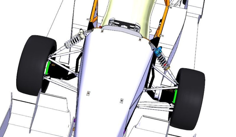 front_suspension_cz5hdv.jpg
2. How Does Adams Car Suspension Software Enhance Vehicle Dynamics Analysis?
Adams Car suspension software significantly enhances vehicle dynamics analysis through its comprehensive simulation capabilities, allowing engineers to predict and optimize vehicle behavior in various driving scenarios.
2.1. Comprehensive Simulation Capabilities
- Full Vehicle Modeling: Adams Car allows engineers to create detailed models of the entire vehicle, including suspension, steering, powertrain, and braking systems. This comprehensive approach enables the analysis of interactions between different systems and their impact on overall vehicle dynamics.
- Realistic Simulation Environment: The software incorporates realistic road profiles, tire models, and aerodynamic forces to simulate real-world driving conditions accurately.
- Advanced Analysis Techniques: Adams Car supports various analysis techniques, including transient response analysis, frequency response analysis, and modal analysis, providing a complete understanding of vehicle behavior.
2.2. Predicting Vehicle Behavior
- Handling Performance: Adams Car helps engineers predict and optimize vehicle handling characteristics, such as steering response, roll stability, and cornering performance. By simulating different driving maneuvers, engineers can identify potential issues and fine-tune suspension parameters to achieve desired handling characteristics.
- Ride Comfort: The software allows engineers to evaluate ride comfort by analyzing suspension vibrations and vehicle body motions. By optimizing suspension parameters, engineers can minimize vibrations and improve ride quality.
- Stability Control: Adams Car can be used to develop and validate stability control systems, such as Electronic Stability Control (ESC) and Anti-lock Braking System (ABS). By simulating emergency maneuvers, engineers can ensure that these systems function effectively and prevent loss of control.
2.3. Optimizing Vehicle Performance
- Suspension Tuning: Adams Car enables engineers to optimize suspension parameters, such as spring rates, damping coefficients, and anti-roll bar stiffness, to achieve desired handling and ride characteristics.
- Component Design: The software helps engineers design and optimize suspension components, such as springs, dampers, and linkages, to meet specific performance requirements.
- System Integration: Adams Car facilitates the integration of different vehicle systems, ensuring that they work together harmoniously to achieve optimal vehicle performance.
2.4. Validating Design Decisions
- Virtual Prototyping: Adams Car allows engineers to create virtual prototypes of vehicle suspension systems and test them under various driving conditions. This reduces the need for physical prototypes, saving time and cost.
- Performance Verification: The software can be used to verify that the vehicle meets performance targets and regulatory requirements.
- Troubleshooting: Adams Car helps engineers identify and resolve potential issues early in the design process, preventing costly delays and rework.
2.5. Integration with Testing
- Correlation with Test Data: Adams Car simulations can be correlated with experimental test data to validate the accuracy of the models and improve the reliability of the predictions.
- Test Case Generation: The software can be used to generate test cases for physical testing, ensuring that the tests cover a wide range of driving conditions and scenarios.
- Data Analysis: Adams Car provides tools for analyzing test data and comparing it with simulation results, providing valuable insights into vehicle behavior.
CAR-REMOTE-REPAIR.EDU.VN provides specialized training in Adams Car, enhancing your skills in vehicle dynamics analysis and remote automotive repair. Address: 1700 W Irving Park Rd, Chicago, IL 60613, United States. Whatsapp: +1 (641) 206-8880.
3. What Are the Benefits of Kinematic and Compliance Analysis in Suspension Design Using Adams Car?
Kinematic and compliance (K&C) analysis in suspension design using Adams Car offers significant benefits, allowing engineers to optimize suspension geometry, improve vehicle handling, and enhance ride comfort through detailed simulation and analysis.
3.1. Optimizing Suspension Geometry
- Wheel Movement Analysis: K&C analysis enables engineers to study the movement of the wheels relative to the vehicle body under various operating conditions. This helps in optimizing suspension geometry to achieve desired wheel travel, camber angles, and toe angles.
- Steering Performance: The software allows engineers to analyze the effect of suspension geometry on steering performance, such as steering effort, steering feel, and steering precision. By optimizing suspension parameters, engineers can improve steering response and enhance driver confidence.
- Roll Center Analysis: K&C analysis provides insights into the location of the roll center and its effect on vehicle stability. By optimizing the roll center location, engineers can minimize body roll and improve vehicle handling.
3.2. Improving Vehicle Handling
- Understeer and Oversteer Characteristics: Adams Car helps engineers predict and control understeer and oversteer characteristics, which are critical for vehicle handling. By optimizing suspension geometry and compliance parameters, engineers can achieve a balanced handling response and improve vehicle stability.
- Transient Response: The software allows engineers to analyze the transient response of the suspension system to sudden inputs, such as steering inputs or road disturbances. This helps in optimizing suspension parameters to minimize oscillations and improve vehicle control.
- Limit Handling: K&C analysis enables engineers to study vehicle behavior at the limits of adhesion, such as during hard cornering or emergency maneuvers. This helps in optimizing suspension parameters to maximize grip and prevent loss of control.
3.3. Enhancing Ride Comfort
- Suspension Travel: Adams Car helps engineers optimize suspension travel to provide adequate clearance for the wheels and prevent bottoming out. This improves ride comfort and protects suspension components from damage.
- Vibration Isolation: The software allows engineers to analyze the effect of suspension compliance on vibration isolation. By optimizing suspension parameters, engineers can minimize vibrations transmitted to the vehicle body and improve ride quality.
- Road Noise: K&C analysis can be used to study the effect of suspension geometry and compliance on road noise. By optimizing suspension parameters, engineers can reduce road noise and improve cabin comfort.
3.4. Compliance Effects
- Bushings and Joints: Adams Car allows engineers to model the compliance of suspension bushings and joints accurately. This is important because compliance can significantly affect suspension kinematics and vehicle dynamics.
- Load Sensitivity: The software helps engineers analyze the load sensitivity of suspension parameters, such as camber angle and toe angle. This is important because suspension parameters can change under load, affecting vehicle handling and stability.
- Durability: K&C analysis can be used to assess the durability of suspension components by simulating real-world driving conditions and calculating stress and strain levels.
3.5. Design Validation
- Virtual Testing: Adams Car allows engineers to perform virtual testing of suspension designs under various operating conditions. This reduces the need for physical prototypes and accelerates the design process.
- Performance Prediction: The software provides accurate predictions of vehicle handling and ride comfort, allowing engineers to validate design decisions and optimize suspension parameters.
- Troubleshooting: K&C analysis helps engineers identify and resolve potential issues early in the design process, preventing costly delays and rework.
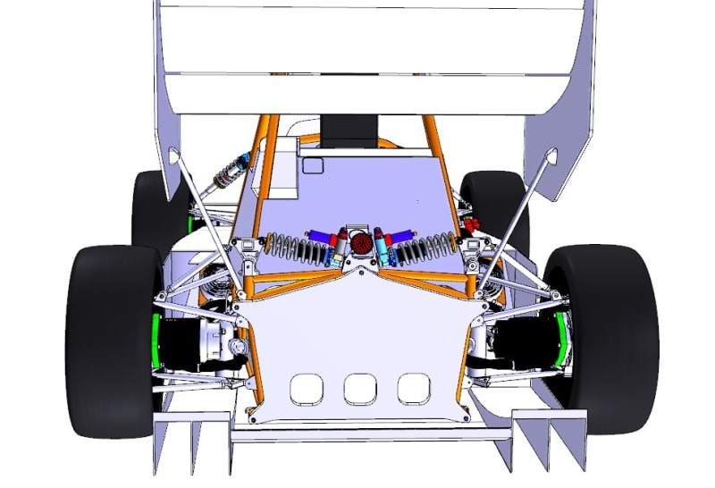 rear_supension_f4glvg.jpg
4. What Are the Key Steps in Setting Up a Suspension Model in Adams Car?
Setting up a suspension model in Adams Car involves several key steps to ensure accurate and reliable simulation results. Here’s a detailed breakdown:
4.1. Defining the Scope and Objectives
- Identify Goals: Clearly define the objectives of the simulation, such as analyzing ride comfort, handling performance, or suspension durability.
- Determine Requirements: Identify the specific requirements for the suspension model, such as the level of detail, accuracy, and computational efficiency.
4.2. Gathering Data
- CAD Data: Obtain CAD data of the suspension components, including geometry, dimensions, and material properties.
- Experimental Data: Collect experimental data, such as suspension characteristics, vehicle test data, and road profiles.
- Design Specifications: Gather design specifications for the suspension system, including spring rates, damping coefficients, and bushing stiffness.
4.3. Creating the Model
- Import Geometry: Import the CAD data into Adams Car and create a geometric representation of the suspension components.
- Define Parts: Define the individual parts of the suspension system, such as springs, dampers, linkages, and bushings.
- Create Joints: Create joints to connect the parts and define their relative motion. Use appropriate joint types, such as revolute, spherical, and translational joints.
- Define Constraints: Define constraints to represent how the suspension system is connected to the vehicle chassis and wheels.
- Assign Properties: Assign material properties, such as density, stiffness, and damping, to the suspension components.
4.4. Modeling Components
- Springs: Model springs using appropriate spring elements, such as linear or non-linear springs. Define the spring rate and pre-load.
- Dampers: Model dampers using appropriate damper elements, such as viscous or frictional dampers. Define the damping coefficient.
- Bushings: Model bushings using appropriate bushing elements, such as linear or non-linear bushings. Define the stiffness and damping properties.
- Tires: Model tires using appropriate tire models, such as Pacejka or MF-Swift models. Define the tire properties, such as stiffness, damping, and friction coefficients.
4.5. Applying Loads and Boundary Conditions
- Road Profiles: Apply realistic road profiles to the wheels to simulate driving conditions.
- External Forces: Apply external forces, such as gravity, aerodynamic forces, and braking forces, to the suspension system.
- Boundary Conditions: Define boundary conditions to represent how the vehicle is supported and constrained.
4.6. Running Simulations
- Define Simulation Parameters: Define the simulation parameters, such as the simulation time, time step, and solver settings.
- Run Simulations: Run the simulations and monitor the progress.
- Troubleshoot Errors: Troubleshoot any errors or warnings that occur during the simulations.
4.7. Analyzing Results
- Post-Processing: Post-process the simulation results to extract relevant data, such as wheel travel, suspension forces, and vehicle body motions.
- Visualization: Visualize the simulation results using plots, animations, and other graphical tools.
- Validation: Validate the simulation results by comparing them with experimental data or theoretical predictions.
4.8. Iterating and Optimizing
- Identify Issues: Identify any issues or areas for improvement in the suspension design.
- Modify the Model: Modify the suspension model to address the identified issues.
- Re-Run Simulations: Re-run the simulations and analyze the results.
- Repeat: Repeat the process until the suspension design meets the specified requirements.
5. How Can You Model Different Suspension Types in Adams Car?
Adams Car provides flexible modeling tools to represent a wide array of suspension designs, from simple to complex. The key is understanding how to use Adams Car’s features to accurately capture the behavior of each suspension type.
5.1. MacPherson Strut Suspension
- Components:
- Strut: Modeled as a combination of a spring, damper, and a revolute joint.
- Lower Control Arm: Modeled as a rigid body connected to the chassis and the strut with revolute joints.
- Spindle: Modeled as a rigid body connected to the strut with a revolute joint.
- Modeling Steps:
- Create the strut assembly with the spring and damper elements.
- Connect the lower control arm to the chassis and strut using revolute joints.
- Define the kinematic hardpoints to match the suspension geometry.
- Constrain the strut’s upper end to allow vertical movement and rotation.
5.2. Double Wishbone Suspension
- Components:
- Upper and Lower Wishbones: Modeled as rigid bodies connected to the chassis and spindle with revolute joints.
- Spring and Damper: Modeled as spring and damper elements connecting the lower wishbone to the chassis.
- Spindle: Modeled as a rigid body connected to the wishbones with revolute joints.
- Modeling Steps:
- Create the upper and lower wishbones with defined geometry.
- Connect the wishbones to the chassis and spindle using revolute joints.
- Place the spring and damper elements between the lower wishbone and the chassis.
- Define the kinematic hardpoints to achieve the desired suspension characteristics.
5.3. Multi-Link Suspension
- Components:
- Multiple Links: Modeled as rigid bodies connected to the chassis and spindle with revolute joints.
- Spring and Damper: Modeled as spring and damper elements connecting one of the links to the chassis.
- Spindle: Modeled as a rigid body connected to the links with revolute joints.
- Modeling Steps:
- Create each link with defined geometry and connection points.
- Connect the links to the chassis and spindle using revolute joints.
- Place the spring and damper elements between one of the links and the chassis.
- Adjust the link geometry and connection points to achieve the desired kinematic behavior.
5.4. Solid Axle Suspension
- Components:
- Axle Housing: Modeled as a rigid body.
- Leaf Springs or Coil Springs: Modeled as spring elements connecting the axle housing to the chassis.
- Dampers: Modeled as damper elements connecting the axle housing to the chassis.
- Control Arms (if applicable): Modeled as rigid bodies connected to the axle housing and chassis with revolute joints.
- Modeling Steps:
- Create the axle housing as a rigid body.
- Connect the axle housing to the chassis using leaf springs or coil springs.
- Place the damper elements between the axle housing and the chassis.
- If using control arms, connect them to the axle housing and chassis using revolute joints.
5.5. Air Suspension
- Components:
- Air Springs: Modeled as spring elements with variable stiffness based on air pressure.
- Dampers: Modeled as damper elements connecting the suspension components to the chassis.
- Height Sensors: Modeled to provide feedback on vehicle ride height.
- Control System: Modeled to adjust air pressure in the springs based on sensor feedback.
- Modeling Steps:
- Create air springs with properties that can be adjusted based on air pressure.
- Incorporate height sensors to measure vehicle ride height.
- Implement a control system to adjust air pressure based on sensor feedback.
- Connect the suspension components to the chassis and spindle using appropriate joints.
5.6. Torsion Bar Suspension
- Components:
- Torsion Bar: Modeled as a torsional spring element.
- Control Arms: Modeled as rigid bodies connected to the torsion bar and spindle with revolute joints.
- Anchor Points: Modeled as fixed points where the torsion bar is anchored to the chassis.
- Modeling Steps:
- Create the torsion bar as a torsional spring element with defined stiffness.
- Connect the control arms to the torsion bar and spindle using revolute joints.
- Anchor the torsion bar to the chassis at fixed points.
By following these steps and utilizing Adams Car’s flexible modeling tools, you can accurately represent a wide variety of suspension types and analyze their performance under different operating conditions. This capability is crucial for optimizing vehicle dynamics and enhancing overall vehicle performance.
6. What Is the Role of Bushings and Joints in Adams Car Suspension Simulations?
Bushings and joints play a crucial role in Adams Car suspension simulations, influencing the accuracy and realism of the results. They connect suspension components and dictate how forces and motions are transmitted through the system.
6.1. Bushings
Bushings are flexible elements that connect suspension components, providing damping and compliance. They affect ride comfort, handling, and noise, vibration, and harshness (NVH) characteristics.
- Modeling Bushings in Adams Car:
- Linear Bushings: Simple models that represent stiffness and damping with constant coefficients. They are suitable for low-frequency analyses.
- Non-Linear Bushings: Account for non-linear stiffness and damping characteristics, providing more accurate results for large displacements and high-frequency vibrations.
- Detailed Bushings: Utilize finite element (FE) models to represent the complex behavior of bushings accurately. They are suitable for detailed analyses but require more computational resources.
- Impact of Bushings on Simulation Results:
- Ride Comfort: Bushings dampen vibrations and reduce harshness, improving ride comfort.
- Handling: Bushings affect steering response and vehicle stability, influencing handling performance.
- NVH: Bushings isolate vibrations and reduce noise transmission, improving NVH characteristics.
6.2. Joints
Joints define the kinematic relationships between suspension components, dictating how they move relative to each other. They affect suspension geometry, wheel travel, and vehicle dynamics.
- Common Joint Types in Adams Car:
- Revolute Joints: Allow rotation about a single axis, used for connecting control arms and spindles.
- Spherical Joints: Allow rotation about three axes, used for connecting ball joints and tie rod ends.
- Translational Joints: Allow linear movement along a single axis, used for modeling sliding elements.
- Fixed Joints: Constrain all degrees of freedom, used for connecting rigidly mounted components.
- Impact of Joints on Simulation Results:
- Suspension Kinematics: Joints define the motion of suspension components, affecting wheel travel, camber angle, and toe angle.
- Vehicle Dynamics: Joints influence vehicle handling, stability, and steering response.
- Load Distribution: Joints affect the distribution of forces and moments within the suspension system.
6.3. Best Practices for Modeling Bushings and Joints
- Accurate Representation:
- Use appropriate bushing and joint models that accurately represent the behavior of the physical components.
- Consider non-linear effects, such as stiffness and damping variations with displacement and frequency.
- Proper Parameter Identification:
- Identify bushing and joint parameters accurately using experimental testing or FE analysis.
- Ensure that the parameters are consistent with the material properties and geometry of the components.
- Validation:
- Validate the simulation results by comparing them with experimental data or theoretical predictions.
- Adjust the bushing and joint models as needed to improve the accuracy of the simulations.
6.4. Examples of Bushing and Joint Applications
- Control Arm Bushings: Connect control arms to the chassis and spindle, providing damping and compliance.
- Shock Absorber Bushings: Connect shock absorbers to the chassis and suspension components, isolating vibrations.
- Ball Joints: Connect control arms to the spindle, allowing articulation and load transfer.
- Tie Rod Ends: Connect tie rods to the steering knuckle, enabling steering inputs.
CAR-REMOTE-REPAIR.EDU.VN provides comprehensive training in Adams Car, focusing on accurate modeling of bushings and joints. Visit us at 1700 W Irving Park Rd, Chicago, IL 60613, United States, or contact us via Whatsapp at +1 (641) 206-8880.
7. What Techniques Can Be Used for Validating Adams Car Suspension Models?
Validating Adams Car suspension models is crucial to ensure the accuracy and reliability of simulation results. Several techniques can be employed to compare simulation results with experimental data and theoretical predictions.
7.1. Experimental Testing
- Hardware-in-the-Loop (HIL) Simulation:
- Integrate the Adams Car suspension model with real-time hardware components, such as electronic control units (ECUs) and sensors.
- Test the integrated system under various operating conditions and compare the simulation results with the hardware measurements.
- Full Vehicle Testing:
- Conduct full vehicle tests on a proving ground or test track.
- Measure parameters such as wheel travel, suspension forces, and vehicle body motions.
- Compare the experimental data with the Adams Car simulation results to validate the model.
7.2. Component Testing
- Suspension Component Testing:
- Test individual suspension components, such as springs, dampers, and bushings, in a laboratory setting.
- Measure their force-displacement characteristics and compare them with the corresponding Adams Car model parameters.
- Modal Testing:
- Perform modal testing on the suspension system to identify its natural frequencies and mode shapes.
- Compare the experimental modal data with the modal analysis results from the Adams Car model.
7.3. Theoretical Analysis
- Kinematic Analysis:
- Perform kinematic analysis of the suspension system to determine its wheel travel, camber angle, and toe angle characteristics.
- Compare the theoretical kinematic data with the corresponding Adams Car simulation results.
- Compliance Analysis:
- Perform compliance analysis of the suspension system to determine its stiffness and damping properties.
- Compare the theoretical compliance data with the corresponding Adams Car model parameters.
7.4. Data Correlation
- Data Alignment:
- Align the experimental data and simulation results in time and frequency domains.
- Use appropriate filtering and smoothing techniques to reduce noise and improve data quality.
- Statistical Analysis:
- Perform statistical analysis to quantify the correlation between the experimental data and simulation results.
- Calculate correlation coefficients, root mean square (RMS) errors, and other statistical metrics to assess the model accuracy.
- Model Updating:
- Update the Adams Car model parameters based on the data correlation results.
- Adjust the model parameters to minimize the differences between the experimental data and simulation results.
- Iterate the validation process until the model accuracy meets the specified requirements.
7.5. Sensitivity Analysis
- Parameter Sensitivity Analysis:
- Perform sensitivity analysis to identify the model parameters that have the greatest impact on the simulation results.
- Focus the validation efforts on the most sensitive parameters to improve the model accuracy.
- Robustness Analysis:
- Perform robustness analysis to assess the sensitivity of the simulation results to variations in the model parameters.
- Ensure that the model is robust and provides reliable results under various operating conditions.
8. How Can Adams Car Be Integrated with Other CAE Software?
Integrating Adams Car with other Computer-Aided Engineering (CAE) software enhances simulation capabilities, streamlines workflows, and allows for more comprehensive analysis of vehicle systems.
8.1. Finite Element Analysis (FEA) Software
- Data Transfer:
- Transfer data between Adams Car and FEA software, such as ANSYS or Abaqus, to simulate structural behavior of suspension components.
- Export Adams Car simulation results, such as forces and displacements, as boundary conditions for FEA analysis.
- Import FEA results, such as stress and strain distributions, into Adams Car to assess the durability of suspension components.
- Co-Simulation:
- Perform co-simulation between Adams Car and FEA software to simulate the dynamic interaction between the suspension system and the structural components.
- Use Adams Car to simulate the vehicle dynamics and FEA software to simulate the structural behavior of the suspension components simultaneously.
8.2. Computational Fluid Dynamics (CFD) Software
- Aerodynamic Analysis:
- Integrate Adams Car with CFD software, such as Fluent or STAR-CCM+, to simulate the aerodynamic effects on vehicle dynamics.
- Export vehicle body motions from Adams Car as inputs for CFD analysis to calculate aerodynamic forces and moments.
- Import aerodynamic forces and moments from CFD analysis into Adams Car to simulate their effects on vehicle handling and stability.
- Thermal Analysis:
- Integrate Adams Car with CFD software to simulate the thermal behavior of suspension components.
- Export suspension component temperatures from CFD analysis into Adams Car to simulate their effects on material properties and performance.
8.3. Control Systems Software
- Model-Based Design:
- Integrate Adams Car with control systems software, such as MATLAB/Simulink, to design and validate control algorithms for suspension systems.
- Export Adams Car suspension models as plant models for control system design in MATLAB/Simulink.
- Import control algorithms from MATLAB/Simulink into Adams Car to simulate their effects on vehicle dynamics.
- Hardware-in-the-Loop (HIL) Simulation:
- Integrate Adams Car with HIL simulation platforms to test control algorithms in a real-time environment.
- Use Adams Car to simulate the vehicle dynamics and HIL simulation platforms to simulate the control system hardware.
8.4. CAD Software
- Data Exchange:
- Integrate Adams Car with CAD software, such as CATIA or SolidWorks, to exchange geometric data of suspension components.
- Import CAD models of suspension components into Adams Car to create simulation models.
- Export simulation results from Adams Car to CAD software to visualize the behavior of suspension components.
- Design Optimization:
- Integrate Adams Car with CAD software to optimize the design of suspension components based on simulation results.
- Use optimization algorithms to automatically adjust the CAD model parameters to improve the performance of the suspension system.
8.5. Multi-Physics Simulation Software
- Coupled Analysis:
- Integrate Adams Car with multi-physics simulation software to simulate the coupled behavior of multiple physical phenomena.
- Simulate the interaction between vehicle dynamics, structural mechanics, fluid dynamics, and thermal behavior simultaneously.
- Virtual Prototyping:
- Use multi-physics simulation to create virtual prototypes of vehicle systems that accurately represent their behavior under various operating conditions.
- Reduce the need for physical prototypes and accelerate the design process.
By integrating Adams Car with other CAE software, engineers can perform more comprehensive and accurate simulations of vehicle systems, leading to improved designs and enhanced performance.
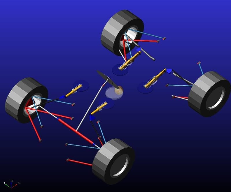 bellcranks_on_front_and_rear_suspension_v8b2if.jpg
9. What Are the Advanced Features of Adams Car for Suspension Analysis?
Adams Car offers several advanced features for detailed suspension analysis, allowing engineers to go beyond basic simulations and explore complex aspects of vehicle dynamics.
9.1. Flexbody Analysis
- Flexible Components:
- Model suspension components as flexible bodies to account for their structural deformation under load.
- Import finite element (FE) models of suspension components into Adams Car to represent their flexibility.
- Accurate Results:
- Capture the effects of structural flexibility on suspension kinematics, compliance, and vehicle dynamics.
- Obtain more accurate simulation results for high-frequency vibrations and dynamic loads.
9.2. Co-Simulation with Control Systems
- Real-Time Control:
- Integrate Adams Car with control systems software to simulate the real-time interaction between the suspension system and the control algorithms.
- Model active suspension systems, such as electronic dampers and air springs, and their control strategies.
- Model-Based Design:
- Use model-based design techniques to develop and validate control algorithms for suspension systems.
- Optimize the control algorithms to improve vehicle handling, ride comfort, and stability.
9.3. Design of Experiments (DOE)
- Parameter Optimization:
- Use DOE techniques to systematically vary the suspension parameters and evaluate their effects on the vehicle performance.
- Identify the optimal combination of suspension parameters that meets the design objectives.
- Sensitivity Analysis:
- Perform sensitivity analysis to determine the parameters that have the greatest impact on the simulation results.
- Focus the design efforts on the most sensitive parameters to improve the vehicle performance.
9.4. Optimization Algorithms
- Automated Optimization:
- Use optimization algorithms to automatically adjust the suspension parameters to minimize or maximize a specific objective function.
- Optimize the suspension design for various performance criteria, such as ride comfort, handling, and stability.
- Multi-Objective Optimization:
- Perform multi-objective optimization to balance competing design objectives.
- Obtain a set of optimal solutions that represent the trade-offs between different performance criteria.
9.5. User-Defined Subroutines
- Custom Functions:
- Create user-defined subroutines to implement custom functions and models in Adams Car.
- Model complex suspension components, such as non-linear dampers and variable stiffness springs.
- Enhanced Flexibility:
- Enhance the flexibility of Adams Car and tailor it to specific simulation needs.
- Develop custom analysis techniques and post-processing tools.
9.6. Advanced Tire Models
- Accurate Tire Behavior:
- Use advanced tire models, such as Pacejka or MF-Swift, to accurately simulate the tire behavior under various operating conditions.
- Capture the effects of tire slip, camber angle, and inflation pressure on the vehicle dynamics.
- Realistic Simulations:
- Obtain more realistic simulation results for vehicle handling and stability.
- Improve the accuracy of the suspension analysis.
10. How Can Training at CAR-REMOTE-REPAIR.EDU.VN Help You Master Suspension Software Adams Car?
Training at CAR-REMOTE-REPAIR.EDU.VN can significantly enhance your skills in using suspension software Adams Car through comprehensive courses and hands-on experience.
10.1. Comprehensive Curriculum
- Fundamentals:
- Understand the fundamentals of multibody dynamics and vehicle dynamics.
- Learn the basics of Adams Car software and its applications in suspension analysis.
- Advanced Techniques:
- Explore advanced techniques for modeling suspension systems in Adams Car.
- Learn how to use flexbody analysis, co-simulation with control systems, and optimization algorithms.
- Real-World Applications:
- Apply Adams Car to solve real-world suspension design problems.
- Work on case studies and projects that simulate industry scenarios.
10.2. Hands-On Experience
- Practical Exercises:
- Participate in practical exercises and workshops to gain hands-on experience with Adams Car.
- Learn how to create suspension models, run simulations, and analyze results.
- Project-Based Learning:
- Work on project-based learning assignments to apply your knowledge and skills.
- Develop your own suspension models and simulate their performance under various operating conditions.
10.3. Expert Instructors
- Industry Professionals:
- Learn from expert instructors who have extensive experience in the automotive industry.
- Benefit from their practical insights and real-world knowledge.
- Personalized Guidance:
- Receive personalized guidance and feedback from the instructors.
- Get answers to your questions and address your specific learning needs.
10.4. State-of-the-Art Facilities
- Advanced Software:
- Access state-of-the-art computer labs equipped with the latest version of Adams Car software.
- Use advanced simulation tools to analyze suspension systems.
- Dedicated Resources:
- Utilize dedicated resources, such as online tutorials, documentation, and support forums.
- Enhance your learning experience.
10.5. Career Advancement
- Job Opportunities:
- Increase your job opportunities in the automotive industry by mastering Adams Car software.